Monday, February 15, 2010

Introduction

COURSE OUTLINE


1. Department: Electrical and Allied Department

2. Course code: ECE 3A

3. Course title: Electromagnetics

4. Course Description
Deals with the study of vector analysis; steady electric and magnetic fields; dielectric and magnetic materials; coupled circuits; magnetic circuits; time- varying fields; Maxwell's equations; field and circuit relationships.

5. Course Objectives
At the end of the course, the students shall be able to:

a. Explain the behavior of charged particles in free space.
b. Analyze systems in electric and magnetic fields.
c. Solve problems about field and circuit relationships.

6. Unit Credit/ Time Allotment
Lecture: 3 units, (3.75 hrs/wk; 14 weeks per term)

7. Semester/ Term Offered: 2nd Term

8. Pre- requisite Subject/s: Math 6

9. Co- requisite Subject/s: EE1

10. Clientele: Bachelor of Science in Electrical Engineering

11. Requirements:

The requirements of this course and corresponding inputs into the final grade are as follows:

a. Quizzes, seatwork, homework, recitation, attendance . . . 30 %
b. Unit Test and actual exercises . . . . . . . . . . . . . . . . .. . . . 40 %
c. Term Test . . . . . . . . . . . . . . . . . . . . . . . . . . . . . . . . . . . 30 %
TOTAL . . . . . . . . . . . . . . . . . . . . . . . . . . . . . . . . . . . . . 100 %


I. Vector Analysis
1. Introduction
2. Vector Algebra
3. Coordinate System and Transformation

II. Coulomb's Law and Electric Field Intensity
1. Coulomb's Law
2. Electric Field Intensity
3. Streamlines and Sketches

III. Application
1. Electric Flux Density
Faraday's Law
2. Gauss' Law
3. Divergence

IV. Current, Conductors and Dielectrics
1. Current and Current Density
2. Continuity of Current
3. Conductor Properties
4. Nature of Dielectrics

V. Application
1. Biot- Savart Law and Magnetic Field Intensity
2. Ampere's Law
3. Capacitance, Resistance, Inductance
4. Maxwell's Equation


ELECTROMAGNETICS

It deals with the study of vector analysis; steady electric and magnetic fields; dielectric and magnetic materials; coupled circuits; magnetic circuits; time- varying fields; Maxwell's equations; field and circuit relationships.


Electromagnetism is one of the four virtual photons of nature. It is the force that affects electrically charged particles, and is reciprocally affected by the presence and motion of such particles. The areas in which this happens are called electromagnetic fields, a type of field. The electromagnetic force operates via the exchange of messenger particles called photons and virtual photons. The exchange of messenger particles between bodies acts to create the perceptual force whereby instead of just pushing or pulling particles apart, the exchange changes the character of the particles that swap them.

Electromagnetism is the force responsible for practically all the phenomena encountered in daily life (with the exception of gravity). All the forces involved in interactions between electrons can be traced to electromagnetism acting on the electrically charged protons and electrons inside the atoms. This includes the forces we experience in "pushing" or "pulling" ordinary material objects (such as coffee cups), which come from the intermolecular forces between the individual molecules in our bodies and those in the objects.

Electromagnetism is also the force which holds electrons and protons together in atoms, and which holds atoms together to make molecules, thus governing of the processes involved in chemistry, which arise from interactions between the electrons orbiting atoms.

The force of electromagnetism is manifestated both in electric fields and magnetic fields; both are simply different aspects of electromagnetism, and hence are intrinsically related to each other. Thus, a changing electric field generates a magnetic field; coversely a changing magnetic field generates an electric field. This effect is called electromagnetic induction, and is the basis of operation for electrical generators, induction motors, and transformers. Mathematically speaking, magnetic fields and electric fields are convertible with relative motion as a four vector.

Electric fields are the cause of several common phenomena, such as electric potential (such as the voltage of a battery), electric current (such as the flow of electricity through a flashlight), and electric fields. Magnetic fields are the cause of the force associated with magnets.

The theoretical implications of electromagnetism led to the development of special relativity by Albert Einstein in 1905.

Originally, electricity and magnetism were thought of as two separate forces. This view changed, however, with the publication of James Clerk Maxwell's 1873 Treatise on Electricity and Magnetism in which the interactions of positive and negative charges were shown to be regulated by one force. There are four main effects resulting from these interactions, which have been clearly demonstrated by experiment:

  1. Electric charges attract or repel one another with a force inversely proportional to the square of the distance between them: unlike charges attract, like ones repel.
  2. Magnetic poles (or states of polarization at individual points) attract or repel one another in a similar way and always come in pairs: every north pole is yoked to a south pole.
  3. An electric current in a wire creates a circular magnetic field around the wire, its direction depending on that of the current.
  4. A current is induced in a loop of wire when it is moved towards or away from a magnetic field, or a magnet is moved towards or away from it, the direction of current depending on that of the movement.

While preparing for an evening lecture on 21 April 1820, Hans Christian Ørsted made a surprising observation. As he was setting up his materials, he noticed a compass needle deflected from magnetic north when the electric current from the battery he was using was switched on and off. This deflection convinced him that magnetic fields radiate from all sides off of a wire carrying an electric current, just as light and heat do, and that it confirmed a direct relationship between electricity and magnetism.

At the time of discovery, Ørsted did not suggest any satisfactory explanation of the phenomenon, nor did he try to represent the phenomenon in a mathematical framework. However, three months later he began more intensive investigations. Soon thereafter he published his findings, proving that an electric current produces a magnetic field as it flows through a wire. The CGS unit of magnetic induction (oersted) is named in honor of his contributions to the field of electromagnetism.

His findings resulted in intensive research throughout the scientific community in electrodynamics. They influenced French physicist André-Marie Ampère's developments of a single mathematical form to represent the magnetic forces between current-carrying conductors. Ørsted's discovery also represented a major step toward a unified concept of energy.

This unification, which was observed by Michael Faraday, extended by James Clerk Maxwell, and partially reformulated by Oliver Heaviside and Heinrich Hertz, is one of the accomplishments of 19th century Mathematical Physics. It had far-reaching consequences, one of which was the understanding of the nature of light. Light and other electromagnetic waves take the form of quantized, self-propagating oscillatory electromagnetic field disturbances called photons. Different frequencies of oscillation give rise to the different forms of electromagnetic radiation, from radio waves at the lowest frequencies, to visible light at intermediate frequencies, to gamma rays at the highest frequencies.

Ørsted was not the only person to examine the relation between electricity and magnetism. In 1802 Gian Domenico Romagnosi, an Italian legal scholar, deflected a magnetic needle by electrostatic charges. Actually, no galvanic current existed in the setup and hence no electromagnetism was present. An account of the discovery was published in 1802 in an Italian newspaper, but it was largely overlooked by the contemporary scientific community.


Vector Analysis

Some physical quantities, such as time, temperature, mass, density and electric charge, can be described completely by a single number with a unit. But many other quantities have a direction associated with them and cannot be described by a single number. A simple example of a quantity with a direction is the motion of an airplane. To describe this motion completely, we must say not only how fast the plane is moving, but also in what direction. The speed of the airplane combined with its direction of motion together, constitute a quantity called velocity. Another example is force, which in physics means a push or pull exerted on a body. Giving a complete description of force means describing both how hard the force pushes or pulls on the body and the direction of the push or pull.


When a physical quantity is described by a single number, we call it a scalar quantity. In contrast, a vector quantity has both a magnitude ( the "how much" or "how big" part) and a direction in space. Calculations with scalar quantities use the operations of ordinary arithmetic.

To understand more about vectors and how they combine, we start with the simplest vector quantity, displacement. Displacement is simply a change in position of a point. ( The point may represent a particle or a small body.)In figure (a) we represent the change in position from point P1 to P2, with an arrowhead at P2 to represent the direction of the motion. Displacement is a vector quantity because we must state not only how far the particle moves, but also in what direction. Walking 3 km north from your front door doesn't get you to the same places as walking 3 km southeast; these two displacements have the same magnitude but different directions.

When drawing any vector, we always draw a line with an arrowhead at its tip. The length of the line shows the vector's magnitude, and the direction of the line shows the vector's direction. Displacement is always a straight- line segment, directed from the starting point to the end point, even though the actual part of the particle may be curved. In figure (b) the particle moves along the curved part shown from P1 to P2, but the displacement is still the vector . Note that the displacement is not related directly to the total distance traveled. If the particle were to continue on P3 and then return to P1, the displacement for the entire trip would be zero.

If two vectors have the same direction, they are called parallel. If they have the same magnitude and the same direction, they are equal, no matter where they are located in space. the vector A' from point P3 to point P4 in the figure above has the same length and direction as the vector A from point P1 to P2. These two displacements are equal, even though they start at different points. We write this as A = A' in the figure above, using a boldface equal sign to emphasize that equality of two vector quantities is not the same relationship as equality of two scalar quantities. two vector quantities are equal only when they have the same magnitude and the same direction.

The vector B in the figure, however, is not equal to vector A because its direction is opposite ti that of vector A, we define the negative of a vector as a vector having the same magnitude as the original vector but the opposite direction. The negative of vector quantity A is denoted as -A, and we use a boldface minus sign to emphasize the vector nature of the quantities. If the vector A is 87 m south, then -A is 87 m north. When two vectors A and B have opposite directions, whether their magnitudes are the same or not, we say that they are antiparallel.

We usually represent the magnitude of a vector quantity ( its length in the case of a displacement vector ) by the same latter used for the vector, but in light italic type with no arrow on top, rather than boldface italic with an arrow ( which is reserved for vectors ). An alternative notation is the vector symbol with vertical bars on both sides.

By definition, the magnitude of vector quantity is a scalar quantity ( a number ) and is always positive. We also note that a vector can never be equal to a scalar because they are different kinds of quantities. The expression "A= 6m" is as wrong as "2 oranges = 3 apples" or "6 lb = 7 km"!

Vector Algebra

Vectors and vector addition:

A scalar is a quantity like mass or temperature that only has a magnitude. On the other hand, a vector is a mathematical object that has magnitude and direction. A line of given length and pointing along a given direction, such as an arrow, is the typical representation of a vector. Typical notation to designate a vector is a boldfaced character, a character with and arrow on it, or a character with a line under it (i.e., ). The magnitude of a vector is its length and is normally denoted by or A.

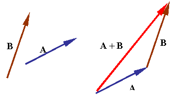
Addition of two vectors is accomplished by laying the vectors head to tail in sequence to create a triangle such as is shown in the figure.

The following rules apply in vector algebra.

where P and Q are vectors and a is a scalar.

The sum of a vector v1 and a vector v2: v1 +v2 or v2 +v1 is a vector whose characteristics are found either by graphical or analytical processes. The vectors v1 and v2 add according to the parallelogram law: v1+v2 is equal to the diagonal of a parallelogram formed by the graphical representation of the vectors. The vector v1 + v2 is called the resultant of v1 and v2. The vectors can be added by moving them successively to parallel positions so that the head of one vector connects to the tail of the next vector. The resultant is the vector whose tail connects to the tail of the first vector, and whose head connects to the head of the last vector.


Vector addition is:


Commutative

the characteristics of the resultant are independent of the order in which the vectors are added (commutativity);

v1 + v2 = v2 + v1.
Associative

the characteristics of the resultant are not affected by the
manner in which the vectors are grouped (associativity);

v1 + (v2 + v3) = (v1 + v2) + v3.


Problem Solving Strategy for Vector Addition

1. First, draw the individual vectors being summed and the coordinate axes being used. in your drawing, place the tail of the first vector at the origin of the coordinates, place the tailof the second vector at the head of the first vector, and so on. Draw the vector sum R (with an arrowhead on top) from the tail of the first vector to the head of the last vector.

2. Find the x-and y- components of each individual vector and record your results in a table. If a vector is described by its magnitude A and its angle, measured from the =x- axis toward the +y- axis. Some components may be positive and some may be negative, depending on how the vector is oriented. If the angles of the vectors are given in some other way, perhaps, using a different reference direction, convert them to angles measured from the +x- axis as described above. Be particularly careful with the signs.

3. Add the individual x- components algebraically, including signs, to find Rx, the x- component of the vector sum. Do the same for the y- components to find Ry.

4. Then the magnitude R and direction angle of the vector sum are given by


Unit vectors

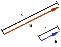
A unit vector is a vector of unit length. A unit vector is sometimes denoted by replacing the arrow on a vector with a "^" or just adding a "^" on a boldfaced character (i.e., ). Therefore,

Any vector can be made into a unit vector by dividing it by its length.

Any vector can be fully represented by providing its magnitude and a unit vector along its direction.

Base vectors and vector components:

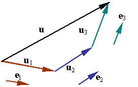
Base vectors are a set of vectors selected as a base to represent all other vectors. The idea is to construct each vector from the addition of vectors along the base directions. For example, the vector in the figure can be written as the sum of the three vectors u1, u2, and u3, each along the direction of one of the base vectors e1, e2, and e3, so that

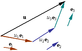
Each one of the vectors u1, u2, and u3 is parallel to one of the base vectors and can be written as scalar multiple of that base. Let u1, u2, and u3 denote these scalar multipliers such that one has

The original vector u can now be written as

The scalar multipliers u1, u2, and u3 are known as the components of u in the base described by the base vectors e1, e2, and e3. If the base vectors are unit vectors, then the components represent the lengths, respectively, of the three vectors u1, u2, and u3. If the base vectors are unit vectors and are mutually orthogonal, then the base is known as an orthonormal, Euclidean, or Cartesian base.

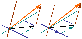
A vector can be resolved along any two directions in a plane containing it. The figure shows how the parallelogram rule is used to construct vectors a and b that add up to c.

In three dimensions, a vector can be resolved along any three non-coplanar lines. The figure shows how a vector can be resolved along the three directions by first finding a vector in the plane of two of the directions and then resolving this new vector along the two directions in the plane.

When vectors are represented in terms of base vectors and components, addition of two vectors results in the addition of the components of the vectors. Therefore, if the two vectors A and B are represented by

then,

Rectangular components in 2-D:

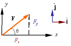
The base vectors of a rectangular x-y coordinate system are given by the unit vectors and along the x and y directions, respectively.

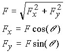
Using the base vectors, one can represent any vector F as

Due to the orthogonality of the bases, one has the following relations.

Rectangular coordinates in 3-D:

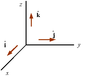
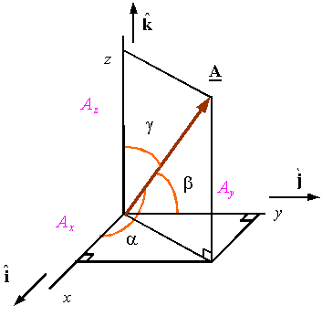
The base vectors of a rectangular coordinate system are given by a set of three mutually orthogonal unit vectors denoted by , , and that are along the x, y, and z coordinate directions, respectively, as shown in the figure.

The system shown is a right-handed system since the thumb of the right hand points in the direction of z if the fingers are such that they represent a rotation around the z-axis from x to y. This system can be changed into a left-handed system by reversing the direction of any one of the coordinate lines and its associated base vector.

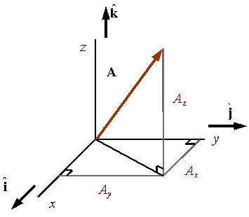
In a rectangular coordinate system the components of the vector are the projections of the vector along the x, y, and z directions. For example, in the figure the projections of vector A along the x, y, and z directions are given by Ax, Ay, and Az, respectively.

As a result of the Pythagorean theorem, and the orthogonality of the base vectors, the magnitude of a vector in a rectangular coordinate system can be calculated by

Direction cosines:

Direction cosines are defined as

where the angles , , and are the angles shown in the figure. As shown in the figure, the direction cosines represent the cosines of the angles made between the vector and the three coordinate directions.

The direction cosines can be calculated from the components of the vector and its magnitude through the relations

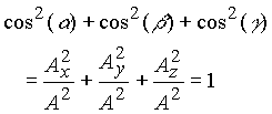
The three direction cosines are not independent and must satisfy the relation

This results form the fact that

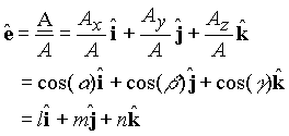
A unit vector can be constructed along a vector using the direction cosines as its components along the x, y, and z directions. For example, the unit-vector along the vector A is obtained from

Therefore,

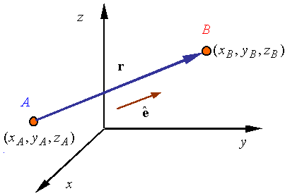
A vector connecting two points:

The vector connecting point A to point B is given by

A unit vector along the line A-B can be obtained from

A vector F along the line A-B and of magnitude F can thus be obtained from the relation

Dot product:

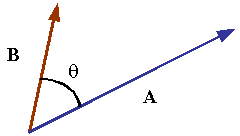
The dot product is denoted by "" between two vectors. The dot product of vectors A and B results in a scalar given by the relation

where is the angle between the two vectors. Order is not important in the dot product as can be seen by the dot products definition. As a result one gets

The dot product has the following properties.

Since the cosine of 90o is zero, the dot product of two orthogonal vectors will result in zero.

Since the angle between a vector and itself is zero, and the cosine of zero is one, the magnitude of a vector can be written in terms of the dot product using the rule

Rectangular coordinates:

When working with vectors represented in a rectangular coordinate system by the components

then the dot product can be evaluated from the relation

This can be verified by direct multiplication of the vectors and noting that due to the orthogonality of the base vectors of a rectangular system one has

Projection of a vector onto a line:

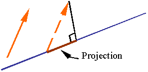
The orthogonal projection of a vector along a line is obtained by moving one end of the vector onto the line and dropping a perpendicular onto the line from the other end of the vector. The resulting segment on the line is the vector's orthogonal projection or simply its projection.

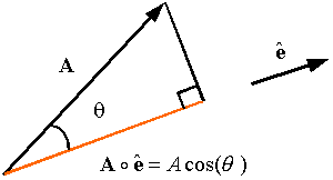
The scalar projection of vector A along the unit vector is the length of the orthogonal projection A along a line parallel to , and can be evaluated using the dot product. The relation for the projection is

The vector projection of A along the unit vector simply multiplies the scalar projection by the unit vector to get a vector along . This gives the relation

The cross product:

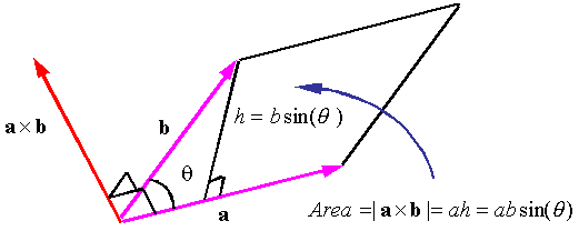
The cross product of vectors a and b is a vector perpendicular to both a and b and has a magnitude equal to the area of the parallelogram generated from a and b. The direction of the cross product is given by the right-hand rule . The cross product is denoted by a "" between the vectors

Order is important in the cross product. If the order of operations changes in a cross product the direction of the resulting vector is reversed. That is,

The cross product has the following properties.

Rectangular coordinates:

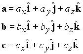
When working in rectangular coordinate systems, the cross product of vectors a and b given by

can be evaluated using the rule

One can also use direct multiplication of the base vectors using the relations

The triple product:

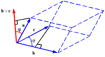
The triple product of vectors a, b, and c is given by

The value of the triple product is equal to the volume of the parallelepiped constructed from the vectors. This can be seen from the figure since

The triple product has the following properties

Rectangular coordinates:

Consider vectors described in a rectangular coordinate system as

The triple product can be evaluated using the relation

EXERCISES

1. A cross- country skier skis 1.00 km north and then 2.00 km east on a horizontal snow field. a.) How far and in what direction is she from the starting point? b.) What are the magnitude and direction of her resultant displacement?