Resistance
The electrical resistance of an object is a measure of its opposition to the passage of a steady electric current. An object of uniform cross section will have a resistance proportional to its length and inversely proportional to its cross-sectional area, and proportional to the resistivity of the material.
Discovered by Georg Ohm in the late 1820s, electrical resistance shares some conceptual parallels with the mechanical notion of friction. The SI unit of electrical resistance is the ohm, symbol Ω. Resistance's reciprocal quantity is electrical conductance measured in siemens, symbol S.
The resistance of a resistive object determines the amount of current through the object for a given potential difference across the object, in accordance with Ohm's law:

where
- R is the resistance of the object, measured in ohms, equivalent to J·s/C2
- V is the potential difference across the object, measured in volts
- I is the current through the object, measured in amperes
For a wide variety of materials and conditions, the electrical resistance does not depend on the amount of current through or the amount of voltage across the object, meaning that the resistance R is constant for the given temperature and material. Therefore, the resistance of an object can be defined as the ratio of voltage to current:

Capacitance
In electromagnetism and electronics, capacitance is the ability of a body to hold an electrical charge. Capacitance is also a measure of the amount of electrical energy stored (or separated) for a given electric potential. A common form of energy storage device is a parallel-plate capacitor. In a parallel plate capacitor, capacitance is directly proportional to the surface area of the conductor plates and inversely proportional to the separation distance between the plates. If the charges on the plates are +Q and –Q, and V gives the voltage between the plates, then the capacitance is given by

The SI unit of capacitance is the farad; 1 farad is 1 coulomb per volt.
The energy (measured in joules) stored in a capacitor is equal to the work done to charge it. Consider a capacitance C, holding a charge +q on one plate and –q on the other. Moving a small element of charge dq from one plate to the other against the potential difference V = q/C requires the work dW:
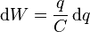
where W is the work measured in joules, q is the charge measured in coulombs and C is the capacitance, measured in farads.
The energy stored in a capacitance is found by integrating this equation. Starting with an uncharged capacitance (q = 0) and moving charge from one plate to the other until the plates have charge +Q and –Q requires the work W:

Where W is in Joules.
Inductance
It is the property in an electrical circuit where a change in the electric current through that circuit induces an electromotive force (EMF) that opposes the change in current
In electrical circuits, any electric current, i, produces a magnetic field and hence generates a total magnetic flux, Φ, acting on the circuit. This magnetic flux, due to Lenz's law, tends to act to oppose changes in the flux by generating a voltage (a back EMF) in the circuit that counters or tends to reduce the rate of change in the current. The ratio of the magnetic flux to the current is called the self-inductance, which is usually simply referred to as the inductance of the circuit. To add inductance to a circuit, electronic components called inductors are used, which consist of coils of wire to concentrate the magnetic field.
The term 'inductance' was coined by Oliver Heaviside in February 1886. It is customary to use the symbol L for inductance, possibly in honour of the physicist Heinrich Lenz.
The SI unit of inductance is the henry (H), named after American scientist and magnetic researcher Joseph Henry. 1 H = 1 Wb/A.
The quantitative definition of the (self-) inductance of a wire loop in SI units (webers per ampere, known as henries) is

where L is the inductance, Φ denotes the magnetic flux through the area spanned by the loop, N is the number of wire turns, and i is the current in amperes. The flux linkage thus is
 .
.
There may, however, be contributions from other circuits. Consider for example two circuits K1, K2, carrying the currents i1, i2. The flux linkages of K1 and K2 are given by

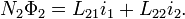
According to the above definition, L11 and L22 are the self-inductances of K1 and K2, respectively. It can be shown (see below) that the other two coefficients are equal: L12 = L21 = M, where M is called the mutual inductance of the pair of circuits.
The number of turns N1 and N2 occur somewhat asymmetrically in the definition above. However, Lmn ia always proportional to the product NmNn, and thus the total currents Nmim contribute to the flux.
Self and mutual inductances also occur in the expression

for the energy of the magnetic field generated by K, electrical circuits where in is the current in the n-th circuit. This equation is an alternative definition of inductance that also applies when the currents are not confined to thin wires so that it is not immediately clear what area is encompassed by the circuit nor how the magnetic flux through the circuit is to be defined.
The definition L = NΦ/i, in contrast, is more direct and more intuitive. It may be shown that the two definitions are equivalent by equating the time derivative of W and the electric power transferred to the system. It should be noted that this analysis assumes linearity, for nonlinear definitions and discussion see nonlinear inductance.

No comments:
Post a Comment